Tuesday, August 12, 2008

Pump Introduction

Pumping of liquids is almost universal in chemical and petrochemical processes. The many different materials being processed require close attention to selection of materials of construction of the various pump parts, shaft sealing, and the hydraulics of the individual problems. A wide variety of pumps types have been developed to satisfy the many special conditions found in chemical plant systems; however, since all of these cannot be discussed here, the omission of some does not mean that they may not be suitable for a service. In general, the final pump selection and performance details are recommended by the manufacturers to meet the conditions specified by the process design engineer. It is important that the designer of the process system be completely familiar with the action of each pump offered for a service in order that such items as control instruments and valves may be properly evaluated in the full knowledge of the system.
A pump is a physical contrivance that is used to deliver fluids from one location to another through conduits. Over the years, numerous pump designs have evolved to meet differing requirements. The basic requirements to define the application are suction and delivery pressures, pressure loss in transmission, and the flow rate. Special requirements may exist in food, pharmaceutical, nuclear, and other industries that impose material selection requirements of the pump. The primary means of transfer of energy to the fluid that causes flow are gravity, displacement, centrifugal force, electromagnetic force, transfer of momentum, mechanical impulse, and a combination of these energy-transfer mechanisms. Gravity and centrifugal force are the most common energy-transfer mechanisms in use.
Pump designs have largely been standardized. based on application experience, numerous standards have come into existence. As special projects and new application situations for pumps develop, these standards will be updated and revised. Common pump standards are:
1. American Petroleum Institute (API) Standard 610, Centrifugal Pumps for Refinery Service.
2. American Waterworks Association (AWWA) E101, Deep Well Vertical Turbine Pumps.
3. Underwriters Laboratories (UL) UL 51, UL343, UL1081, UL448, UL1247.
4. National Fire Protection Agency (NFPA) NFPA-20 Centrifugal Fire Pumps.
5. American Society of Mechanical Engineers (ASME).
6. American National Standards Institute.
7. Hydraulic Institute Standards (Application).
These standards specify design, construction, and testing details such as material selection, shop inspection and tests, drawings and other uses required, clearances, construction procedures, and so on.
The most common types of pumps used in chemical plant are centrifugal and positive displacement. Occasionally regenerative turbine pumps, axial-flow pumps, and ejectors are used.
Modern practice is to use centrifugal rather than positive displacement pumps where possible because they are usually less costly, require less maintenance, and less space. Conventional centrifugal pumps operate at speeds between 1200 and 8000 rpm. Very high speed centrifugal pumps, which can operate up to 23,000 rpm and higher, are used for low-capacity, highhead applications. Most centrifugal pumps will operate with an approximately constant head over a wide range of capacity.
Positive displacement pumps are either reciprocating or rotary. Reciprocating pumps include piston, plunger, and diaphragm types. Rotary pumps are: single lobe, multiple lobe, rotary vane, progressing cavity, and gear types. Positive displacement pumps operate with approximately constant capacities over wide variations in head, hence they usually are installed for services which require high heads at moderate capacities. A special application of small reciprocating pumps in gas processing plants is for injection of fluids (e.g. methanol and corrosion inhibitors) into process streams, where their constant-capacity characteristics are desirable.
Axial-flow pumps are used for services requiring very high capacities at low heads. Regenerative-turbine pumps are used for services requiring small capacities at high heads. Ejectors are used to avoid the capital cost of installing a pump, when a suitable motive fluid (frequently steam) is available, and are usually low-efficiency devices. These kinds of pumps are used infrequently in the gas processing industry.

To properly accomplish a good and thorough ratinghizing of a centrifugal pump, the plant system designer should at a minimum do the following.

1. Understand the fundamentals of performance of the pump itself.
2. Understand the mechanical details required for a pump to function properly in a system.
3. Calculate the friction and any other pressure losses for each "side" of the pump, suction, and discharge.
4. Determine the suction side and discharge side heads for the mechanical system connecting to the pump.
5. Determine the important available net positive suction head (NPSH,) for the pump suction side mechanical system, and compare this to the manufacturer's required net positive suction head (NPSH,) by the pump itself. This requires that the designer makes a tentative actual pump selection of one or more manufacturers in order to use actual numbers.
6. Make allowable corrections to the pump's required NPSH (using charts where applicable) and compare with the available NPSH. The available must always be several feet (mm) greater than the corrected required.
7. Make fluid viscosity corrections to the required performance if the fluid is more viscous than water.
8. Examine specific speed index, particularly if it can be anticipated that future changes in the system may be required.
9. If fluid being pumped is at elevated temperature (usually above 90o F (32.2o C )), check temperature rise in the pump and the minimum flow required through the pump.
10. Make pump brake horsepower corrections for fluids with a specific gravity different from water. Select actual driver (electric motor, usually) horsepower in order that horsepower losses between the driver and the pump shaft will still provide sufficient power to meet the pump's input shaft requirements.
11. If the pump has some unique specialty service or requirements, recognize these in the final sizing and selection. Consult a reliable manufacturer that produces pumps for the type of service and applications and have them verify the analysis of your system's application.

Net Possitive Suction Head (NPSH)


This is an important part of the pump system and should be thought of as a very specialized piping design. Considerable attention must be directed to the pump suction piping to ensure satisfactory pump operation.
A pump is designed to handle liquid, not vapor, except possibly some vapor entrained or absorbed in the liquid. The liquid or its gases must not vaporize in the eye/entrance of the impeller. (This is the lowest pressure location in the impeller.) Unfortunately, for many situations, it is easy to get vapor into the pump if the design is not carefully done. Vapor forms if the pressure in the pump falls below the liquid’s vapor pressure. The lowest pressure occurs right at the impeller inlet where a sharp pressure dip occurs. The impeller rapidly builds up the pressure, which collapses vapor bubbles, causing cavitation and damage. This must be avoided by maintaining sufficient net positive suction head (NPSH) as specified by the manufacturer.
Net positive suction head (in feet (m) of liquid absolute) above the vapor pressure of the liquid at the pumping temperature is the absolute pressure available at the pump suction flange, and is a very important consideration in selecting a pump which might handle liquids at or near their boiling points, or liquids of high vapor pressures.
Do not confuse NPSH with suction head, as suction head refers to pressure above atmospheric. If this consideration of NPSH is ignored the pump may well be inoperative in the system, or it may be on the borderline and become troublesome or cavitating. The significance of NPSH is to ensure sufficient head of liquid at the entrance of the pump impeller to overcome the internal flow losses of the pump. This allows the pump impeller to operate with a full “bite” of liquid essentially free of flashing bubbles of vapor due to boiling action of the fluid.
The pressure at any point in the suction line must never be reduced to the vapor pressure of the liquid. Both the suction head and the vapor pressure must be expressed in feet (m) of the liquid, and as gauge pressure or absolute pressure.
For low NPSHA (available) (less than 10 ft or 3 m) the pump suction connection and impeller eye may be considerably oversized when compared to a pump not required to handle fluid under these conditions.
Poor suction condition due to inadequate NPSHA is one major contribution to cavitation in pump impellers, and this is a condition at which the pump cannot operate for very long without physical erosion damage to the impeller.


The simple equation to get NPSH value is :

NPSH = (pressure head at the source) + (static suction head) - (friction head in the suction line) - (vapor pressure of the liquid).


Recommendations also are made by the Hydraulic Institute of suction specific speeds for multistage boiler feed pumps, with S = 7900 for single suction and S = 6660 for double suction. Thus the required NPSH can be found by equation :

NPSH = [(rpm)(gpm)0.5/S]4/3

For example, at 3500 rpm, l000 gpm, and S = 7900, the required NPSH is 34 ft
Therefore, the suction system must perform two major jobs: maintain sufficient NPSH; and maintain the pressure above the vapor pressure at all points.
NPSH is the pressure available at the pump suction nozzle after vapor pressure is subtracted. It is expressed in terms of liquid head. It thus reflects the amount of head loss that the pump can sustain internally before the vapor pressure is reached. The manufacturer will specify the NPSH that his pump requires for the operating range of flows when handling water. This same NPSH is normally used for other liquids.
For design work, the known pressure is that in the vessel from which the pump is drawing. Therefore, thepressure and NPSH available at the pump suction flange must be calculated. The vessel pressure and static head pressure are added. From this must be subtracted vapor pressure and any pressure losses in the entire suction system such as:
1. Friction losses in straight pipe, valves, and fittings
2. Loss from vessel to suction line
3. Loss through equipment in the suction line (such as a heat exchanger)
The NPSH requirement must be met for all anticipated flows. Maximum flow will usually have a higher NPSH than normal flow. For some pumps, extremely low flows can also require higher NPSH.
It is usually necessary for the process engineer to have an idea of NPSH requirements early in the design phase of a project. The NPSH sets vessel heights and influences other design aspects. The choice of pumps is an economic balance involving NPSH requirements and pump speed. The lower speed pump will usually have lower NPSH requirements and allow lower vessel heights. A low-speed pump may also have a better maintenance record. However, the higher-speed pump will usually deliver the required head in a cheaper package.
The suction system piping should be kept as simple as reasonably possible and adequately sized. Usually the suction pipe should be larger than the pump suction nozzle.

Nomenclature


Brake Horse Power

The power required to drive the pump is that required to overcome all the losses and supply the energy added to the fluid. These losses include the friction of flow trough the impeller and turbulent losses, the disk friction or energy required just to rotate the impeller in the fluid, the leakage of fluid from the periphery back to the eye of the impeller, and the mechanical friction losses in the bearing, stuffing boxes, and wearing rings.
The liquid horsepower is the energy absorbed in the fluid leaving the pump. The brake horsepower is the energy requirement of the pump per unit of time.


Efficiency

The efficiency of a centrifugal machine is the ratio of the fluid horsepower to brake horsepower.

Cavitation

When a centrifugal pump is operating at high rates, the high velocities occurring at certain points in the eye of the impeller or at the van tips cause local pressures to fall below the vapor pressure of the liquid. Vaporization occurs at this points, forming bubbles which collapse violently upon moving along to a region of higher pressure or lower velocity. This momentary vaporization and destructive collapse of the bubbles is called cavitation and is to be avoided if maximum capacity is to be obtained and damage to the pump prevented. The shock of bubble collapse causes severe pitting of the impeller and creates considerable noise and vibration. Cavitation may be reduced or eliminated by reducing the pumping rate or by slight alterations in impeller design to give better streamlining. Cavitation usually does not occur at low flow rates on any given pump.

Specific Speed

For single-stage side-suction impellers, or one stage of a multistage pump, the specific speed Ns, is a convenient concept.


Ns = specific speed.
N = revolution per second.
Q = volume of fluid per second.
-w = “total developed head”. This value is gotten from Barnoulli equation.

The specific speed is dimensionless if consistent units are used.
The characteristic curves of pump represent performance from zero flow to maximum flow, and the specific speed would vary from zero to infinity, respectively. For classifying impellers a single value must be selected. The point of maximum efficiency is usually selected for calculation of the specific speed. The usual range is from 0.03 to 0.87 when so calculated and expressed as the dimensionless ration given above. The lower values apply to radial-flow centrifugal pumps and the higher specific speeds to axial-flow propeller pumps.
Unfortunately, current practice omits gc and expresses Q in gallons per minute, N in revolutions per minute, and w in foot-pounds force per pound-mass. In these units specific speeds vary from 500 to 15000 which may be converted to the dimensionless ratio by dividing by 17200.


Deep well pump

The centrifugal pump is capable of reduction in size to an extent which permits the construction of a multistage unit which will fit into well casings as small as 4 in. in diameter. Deep well pump assembly can be lowered down to the water level. The motor may be submerged with the pump or kept at the surface level operating trough a long drive shaft extending down to the pump.
A two-stage deep well pump is supported by the discharge piping. Some pumps use no protective tubing around the shaft and depend upon flowing liquid to lubricate rubber shaft bearings mounted at intervals. In the pump illustrated the oil lubricant is sealed from the water by the labyrinth packing.

Sump Pump

These are small single-stage vertical pumps used to drain shallow pits or sumps. They are of the same general construction as vertical process pumps but are not designed for severe operating conditions.

Centrigugal Pump

Basically, the centrifugal machine is built around an impeller, which is in series of radial vanes of various shapes and curvatures, spinning in a circular casing. Fluid enters at the “eye” or axis of rotation and discharges more or less radially into a peripheral chamber at a higher pressure corresponding to the sum of the centrifugal force of rotation and the kinetic energy given to the fluid by the vanes.
The centrifugal pump is the type most widely used in the chemical industry for transferring liquids of all types raw materials, materials in manufacture, and finished products as well as for general services of water supply, boiler feed, condenser circulation, condensate return, etc. These pumps are available through a vast range of sizes, in capacities from 0.5 m3/h to ´ 104 m3/h (2 gal/min to 105 gal/min), and for discharge heads (pressures) from a few meters to approximately 48 MPa (7000 lbf/in2). The size and type best suited to a particular application can be determined only by an engineering study of the problem.
The primary advantages of a centrifugal pump are simplicity, low first cost, uniform (nonpulsating) flow, small floor space, low maintenance expense, quiet operation, and adaptability for use with a motor or a turbine drive.
A centrifugal pump, in its simplest form, consists of an impeller rotating within a casing. The impeller consists of a number of blades, either open or shrouded, mounted on a shaft that projects outside the casing. Its axis of rotation may be either horizontal or vertical, to suit the work to be done. Closed-type, or shrouded, impellers are generally the most efficient. Open- or semiopen-type impellers are used for viscous liquids or for liquids containing solid materials and on many small pumps for general service. Impellers may be of the single-suction or the double-suction type—single if the liquid enters from one side, double if it enters from both sides.
Casings. There are three general types of casings, but each consists of a chamber in which the impeller rotates, provided with inlet and exit for the liquid being pumped. The simplest form is the circular casing, consisting of an annular chamber around the impeller; no attempt is made to overcome the losses that will arise from eddies and shock when the liquid leaving the impeller at relatively high velocities enters this chamber. Such casings are seldom used.
Volute casings take the form of a spiral increasing uniformly in cross-sectional area as the outlet is approached. The volute efficiently converts the velocity energy imparted to the liquid by the impeller into pressure energy.
A third type of casing is used in diffuser-type or turbine pumps. In this type, guide vanes or diffusers are interposed between the impeller discharge and the casing chamber. Losses are kept to a minimum in a well-designed pump of this type, and improved efficiency is obtained over a wider range of capacities. This construction is often used in multistage high-head pumps.


Figure A. A simple centrifugal pump.

Jet Pump

The general term, jet pump, includes all machines whose operation is based on the transfer of energy by impact from a fluid jetting at high velocity into a slowly moving or stagnant fluid, giving the mixture of fluids a moderately high velocity which is then reduced carefully so as to give a final pressure greater then the initial pressure of the low-velocity fluid. An injector is a jet pump using a condensable gas to entrain a liquid and discharging at pressure higher than the initial pressure of the motive fluid or the entrained fluid. It is now practically restricted to boiler feed-water injection. An ejector is a jet pump more general in character, using either gas or liquid for either the motive or the entrained fluid and discharging at a pressure intermediate between the motive pressure and the suction pressure. An exhauster, blower, or compressor is an ejector with gases both the motive and entrained fluids; a siphon is a ejector with gas as the motive fluid and liquid as the entrained fluid; an eductor is an ejector with liquids both as motive and entrained fluid; and a fume absorber is an ejector with liquid as the motive fluid and gas as the entrained liquid.


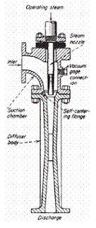
Figure B. Typical steam-jet ejector.

Figure C. Booster ejector with multiple steam nozzles.

An ejector is a simplified type of vacuum pump or compressor which has no pistons, valves, rotors, or other moving parts. Figure B illustrates a steam-jet ejector. It consists essentially of a nozzle which discharges a high-velocity jet across a suction chamber that is connected to the equipment to be evacuated. The gas is entrained by the steam and carried into a venturi-shaped diffuser which converts the velocity energy into pressure energy. Figure C shows a largesized ejector, sometimes called a booster ejector, with multiple nozzles. Nozzles are devices in subsonic flow that have a decreasing area and accelerate the flow. They convert pressure energy to velocity energy. A minimum area is reached when velocity reaches sonic flow. In supersonic flow, the nozzle is an increasing area device. A diffuserin subsonic flow has an increasing area and converts velocity energy into pressure energy. A diffuser in supersonic flow has a decreasing area.
Two or more ejectors may be connected in series or stages. Also, a number of ejectors may be connected in parallel to handle larger quantities of gas or vapor.
Liquid- or air-cooled condensers are usually used between stages. Liquid-cooled condensers may be of either the direct-contact (barometric) or the surface type. By condensing vapor the load on the following stage is reduced, thus minimizing its size and reducing consumption of motive gas. Likewise, a precondenser installed ahead of an ejector reduces its size and consumption if the suction gas contains vapors that are condensable at the temperature condition available. An aftercondenser is frequently used to condense vapors from the final stage, although this does not affect ejector performance
Uses of Ejectors For the operating range of steam-jet ejectors in vacuum applications, see the subsection “Vacuum Systems.”
The choice of the most suitable type of ejector for a given application depends upon the following factors:


1. Steam pressure. Ejector selection should be based upon the minimum pressure in the
supply line selected to serve the unit.
2. Water temperature. Selection is based on the maximum water temperature.
3. Suction pressure and temperature. Overall process requirements should be
considered. Selection is usually governed by the minimum suction pressure required
(the highest vacuum).
4. Capacity required. Again overall process requirements should be considered, but
selection is usually governed by the capacity required at the minimum process
pressure.
Ejectors are easy to operate and require little maintenance. Installation costs are low. Since they have no moving parts, they have long life, sustained efficiency, and low maintenance cost. Ejectors are suitable for handling practically any type of gas or vapor. They are also suitable for handling wet or dry mixtures or gases containing sticky or solid matter such as chaff or dust.
Ejectors are available in many materials of construction to suit process requirements. If the gases or vapors are not corrosive, the diffuser is usually constructed of cast iron and the steam nozzle of stainless steel. For more corrosive gases and vapors, many combinations of materials such as bronze, various stainless-steel alloys, and other corrosion-resistant metals, carbon, and glass can be used.

Jet Pump Design


Jet design is normally handled by the vendor. However, the process engineer must specify the system into which the jets are incorporated. He must also supply the vendor with operating conditions which include :
1. Flows of all components to be purged from thesystem (often air plus water vapor).
2. Temperature and pressure entering the jets and pressureleaving if not atmospheric.
3. Temperature and pressure of steam available to drive the jets.
4. Temperature and quantity of cooling water available for the intercondensers. Also cooling water allowable pressure drop for the intercondensers.
In addition, the process engineer must be aware of good design practices for vacuum jets.


The vendor will convert the component flow data into an "air equivalent." Since jets are rated on air handling ability, he can then build up a system from his standard hardware. The vendor should provide air equivalent capability data with the equipment he supplies. Determination of air equivalent can be done with Equation 1.

(1)


Where

ER = Entrainment ratio (or air equivalent). It is the ratio of the weight of gas handled to the weight of air which would be handled by the same ejector operating under the same conditions.
MW = Gas mol. wt.
F = 1.00, for MW 1 - 30
F = 1.076 - 0.0026 (MW), for MW 3 1 - 140
Equation 1 will give results within 2% of the entrainment ratio curve.
The effect of temperature is shown by Equations 2 and 3.

ERTA = 1 .O 17 - 0.00024T (2)
ERTS = 1.023 - 0.00033T (3)

where
ERTA = The ratio of the weight of air at 70°F to the weight of air at a higher temperature that would be handled by the same ejector operating under the same conditions.
ERTS = Same as above for steam.
T = Gas temperature, "F

The vendor should also supply steam consumption data. However, for initial planning the process engineer needs to have an estimate. Use the following equations to calculate the horsepower required to compress noncondensing components from the jet inlet pressure and temperature to the outlet pressure.


Where

HP = Gas horsepower
W = Flow. lb/min
Hpoly = Polytropic head
HAD = Adiabatic head
EP = Polytropic efficiency
EA = Adiabatic efficiency


where
Z = Average compressibility factor; using 1 .O will
R = 1,544/mol. wt
TI = Suction temperature, R
K = Adiabatic exponent. Cp/Cv. yield conservative results
P1, P2 = Suction, discharge pressures, psia
N = Polytropic exponent.

For process water vapor handled by the jets with intercondensing, calculate horsepower for the first stage only. After the first stage the condenser will bring the system to the same equilibrium as would have occurred without the process water vapor. Use an adiabatic efficiency of 7% for cases with jet intercondensers and 4% for noncondensing cases. Estimate the steam consumption to be the theoretical amount which can deliver the previously calculated total horsepower using the jet system steam inlet and outlet conditions. These ballpark results can be used until vendor data arrive. This procedure will give conservative results for cases with high water vapor compared to the Ludwig’ curves for steam consumption.
Following are some general rules of thumb for jets:
1. To determine number of stages required, assume 7 : 1 compression ratio maximum per stage.
2. The supply steam conditions should not be allowed to vary greatly. Pressure below design can lower capacity. Pressure above design usually doesn’t increase capacity and can even lower capacity.
3. Use Stellite or other hard surface material in the jet nozzle. For example 316s/s is insufficient.
4. Always provide a suitable knockout pot ahead of the jets. Water droplets can quickly damage a jet. The steam should enter the pot tangentially. Any condensate leaves through a steam trap at the bottom. It is a good idea to provide a donut baffle near the top to knock back any water creeping up the vessel walls.
5. The jet barometric legs should go in a straight line to the seal tank. A 60”-90” slope from horizontal is best.


References :


1. Branan, C. R., “The Process Engineer’s Pocket Handbook”, Vol. 2, Gulf Publishing Co., 1983.
2. Brown, G.G., “Unit Operations”, John Wiley and Sons, Inc. , 1950.
3. Evans, E L., “Equipment Design Handbook For- Rejneries and Chemical Plants”, Vol. 1, 2nd Ed., Gulf Publishing Co., 1979.
4. GPSA Engineering Data Book, “Gas Processors Suppliers Association”, Vol. 1, 10th Ed.. 1987.
5. Kern, R., “How to Design Piping for Pump-Conditions,” Chemical Engineering, 1975.
6. Kirk, R.E. and Othmer, D.F., “Ensyclopedia of Chemical Technology”, Interscience Ensyclopedia, Inc. , 1951.
7. Ludwig, E. E., “Applied Process Design for Chemical and Petrochemical Plants” Vol. 1, Gulf Publishing Co., 1977.
8. Perry, R. H., and Chilton, C. H., “Chemical Engineers’ Handbook” New York: McGraw-Hill, Inc, 1973.
9. Standards for Steam Jet Ejectors, 3rd Ed., Heat Exchange Institute, New York, N.Y.
10. WALAS, Stanley M., “Chemical Process Equipment - Selection and Design”, (Butterworth-Heinemann Series in Chemical Engineering). Boston, MA: Butterworth-Heinemann, a division of Reed Publishing (USA) Inc., 1998.